GEOTECHNICAL ENGINEERING1
GLOUCESTER
HomeGeophysicsSeismic tomography (refraction/reflection)

Seismic Tomography for Ground Investigation in Gloucester

Practical geotechnics, field-tested.

LEARN MORE

Gloucester’s historic docks and cathedral close sit on a complex mix of alluvial silts and Triassic mudstones. Urban redevelopment here rarely gets a clean, textbook geology. The city has expanded over buried channels of the Severn, leaving pockets of soft organic clay and loose gravel lenses that standard boreholes can easily miss. That is where seismic tomography earns its place. By measuring the travel time of seismic waves through the subsurface, we build a continuous 2D or 3D velocity profile that reveals hidden boundaries, weathered zones, and depth to competent bedrock. In a city with Gloucester’s layered Quaternary cover, having a geophysical cross-section before committing to intrusive work saves time and avoids surprises during excavation. We frequently pair it with a CPT campaign when the site demands both high-resolution stratigraphy and soil strength parameters for foundation design.

A seismic velocity section reveals what a borehole log cannot—the continuity of layers between points.
Our service areas

How we work

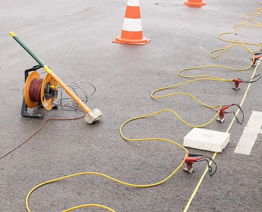
BS 5930:2015+A1:2020 and Eurocode 7 (BS EN 1997-2:2007) set the framework for geophysical ground investigation in the UK. In Gloucester, those standards become particularly relevant because the Lias Clay bedrock often lies beneath variable thicknesses of Cheltenham Sand and gravel. A refraction survey can map the clayhead with good precision, which is essential when designing piled foundations that need a reliable socket length. Our acquisition uses 24-channel seismographs and vertical geophones spaced to match site dimensions. We generate seismic energy with a sledgehammer source on shallow profiles or a weight drop for deeper targets. The data processing workflow includes first-break picking, travel time tomography, and iterative inversion to produce a velocity model. Reflection processing is added when mapping deeper structure or faulting associated with the Malvern Axis, whose influence extends into the Gloucester region. Results are delivered as interpreted cross-sections in depth, not just time. Velocity-to-geology conversion is calibrated against any available borehole logs from the site or BGS records. This approach reduces the number of investigation points needed, which matters on constrained urban lots near the Quays.
Seismic Tomography for Ground Investigation in Gloucester
Technical reference — Gloucester

Local geotechnical context

The superficial deposits along the Severn floodplain include soft alluvium and peat layers that can produce very low seismic velocities, sometimes below 400 m/s. Those materials are prone to differential settlement and amplification during seismic shaking, even if the UK seismicity is moderate. A bigger local concern is the presence of buried river channels filled with loose gravel, which can go undetected by a sparse grid of boreholes. Seismic tomography images these channels as low-velocity anomalies cutting into stiffer material. In the higher parts of the city, where the Lias Clay is shallow, desiccation cracks and weathered zones create a weak near-surface layer that varies in thickness. Mapping that variability helps engineers decide between shallow footings and deeper piling. The risk of not doing a geophysical survey is designing on an assumed layer model that misses a critical lateral change—something we have observed repeatedly on brownfield sites near the canal corridor.

Need a geotechnical assessment?

Reply within 24h.

Email: contact@geotechnical-engineering1.com

Applicable standards

BS 5930:2015+A1:2020 – Code of practice for ground investigations, BS EN 1997-2:2007 (Eurocode 7) – Ground investigation and testing, BS EN ISO 22475-1:2021 – Geotechnical investigation, sampling and groundwater measurement, CIRIA C812 – Guidance on geophysical surveying for ground investigation

Typical values

ParameterTypical value
Survey methodRefraction and/or reflection tomography
Maximum depth of investigationTypically 30–40 m with sledgehammer source
Geophone array24-channel, vertical component, single or spread cable
Data format deliveredSEG-Y, PDF cross-sections, DXF interpretation
P-wave velocity range mapped300–3500 m/s typical for Gloucester strata
Reporting standardBS 5930:2015+A1:2020, factual and interpretive

Frequently asked questions

How much does a seismic tomography survey cost on a typical Gloucester site?

Survey costs depend on line length, target depth and site access conditions. For a typical single-line refraction survey in the Gloucester area, budgets normally fall between £2,120 and £4,330. That includes mobilisation, data acquisition, processing and an engineering report. We provide a fixed quote after reviewing your site location and objectives.

What depth can seismic refraction reach in the Lias Clay around Gloucester?

With a standard sledgehammer source and a 100 m spread length, we typically resolve to depths of 25–35 m in the Lias Clay. The actual penetration depends on the velocity contrast and the energy source. If you need deeper imaging, we can configure a weight drop or discuss reflection processing to extend the depth of investigation.

Does seismic tomography work on paved urban sites in Gloucester?

Yes. We use geophones with steel base plates and a coupling compound to achieve good ground contact on asphalt or concrete. Vehicles and utilities can create noise, so we schedule surveys during quieter periods or use stacking routines to improve signal-to-noise ratio. The method works well on industrial estates and car parks throughout the city.

Location and service area

We serve projects in Gloucester and surrounding areas.

View larger map